


Separator types
Some schematics of typical two- and three-phase separators are shown in horizontal and vertical orientations.Horizontal two-phase separator
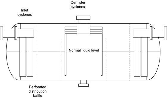
Figs. 1 and 2 illustrate two types of horizontal separators, as can be seen, a weir plate is installed to prevent the gas phase being carry-under to the liquid outlet, and well positioned liquid level to prevent the liquid carry-over from the gas outlet
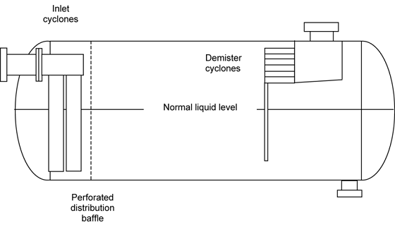
Fig. 1—Horizontal two-phase separator with inlet diverter, perforated distribution baffle, and demister (courtesy of CDS Separation Technologies Inc.).
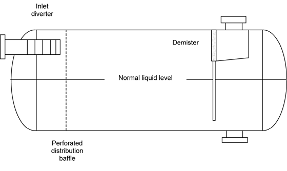
Fig. 2—Horizontal two-phase separator enhanced for foam breaking with inlet cyclones, perforated distribution baffle, and cyclonic demisters (courtesy of CDS Separation Technologies Inc.).
--------
Horizontal double barrel two-phase separator
Figure 3 illustrates a horizontal double barrel two-phase separator, which is used for low liquid rates. A better quality of liquid stream can normally be expected, except for more difficulty and higher cost to build the vessel than the conventional vessel.
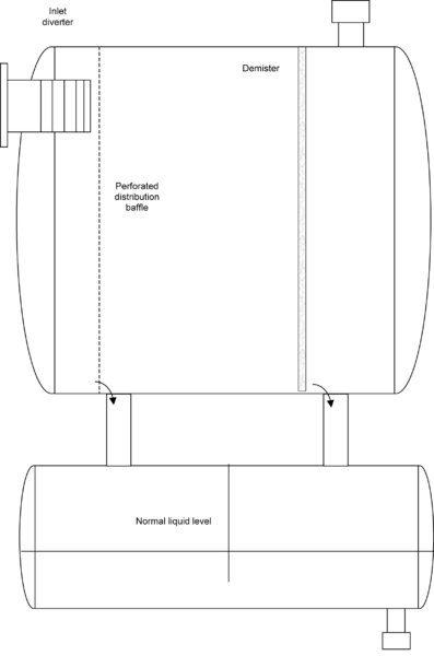
§ Fig. 3—Horizontal double-barrel two-phase separator for low liquid rates (courtesy of CDS Separation Technologies Inc.).
Horizontal three-phase separator
Figs. 4 through 6 illustrate different configurations of horizontal three-phase separators. Compared to the two-phase separator above, additional weir is introduced to control the oil/water interface
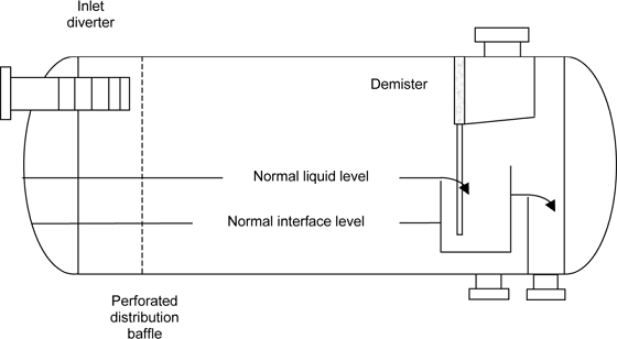
Fig. 4—Horizontal three-phase separator with flooded weir (courtesy of CDS Separation Technologies Inc.).1
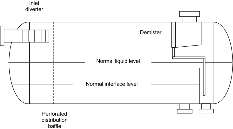
Fig. 4—Horizontal three-phase separator with flooded weir (courtesy of CDS Separation Technologies Inc.).
-------------
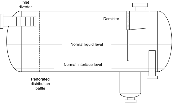
Fig. 6—Horizontal three-phase separator with boot for low water rates (courtesy of CDS Separation Technologies Inc.).
----------
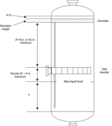
Vertical two-phase separator
Fig. 7 shows a vertical two-phase separator with inlet diverter and demister. The inlet stream gets into the vessel from inlet device. After separation, the liquid phase drops down to the vessel bottom while gas phase floats up to the vessel top
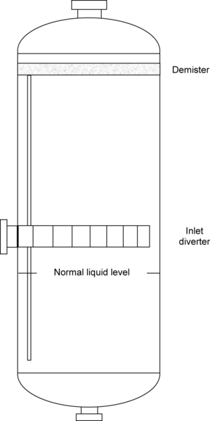
Fig. 7—Vertical two-phase separator with inlet diverter and demister (courtesy of CDS Separation Technologies Inc.).
-----------
Vertical three-phase separator
Fig. 8 illustrates a vertical three-phase separator configured with inlet diverter and demister. After the inlet deverter, the separated gas flows up to the gas outlet, while the liquid phase (oil/water mixture) get into the liquid space through a down comer, where the oil/water are further separated and collected at the each outlet.
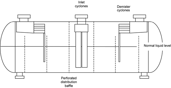
Fig. 8—Vertical three-phase separator with inlet diverter and demister (courtesy of CDS Separation Technologies Inc.).
-------------
Central inlet separator
Fig. 9a is a schematic of a central inlet and dual outlet separator. This design is equivelent to combine two identical separators in parallel. Its main feature is to double the overall throughput at a reduced cost in manufacture, installation, and operation of the vessel.
ig. 9a—Two-phase separator with center inlet cyclones and dual outlets for a floating structure (courtesy of CDS Separation Technologies Inc.).
---------
Dual-inlet, central-outlet separator
Fig. 9b is a dual-inlet, central-outlet separator. The liquid level in the center of the vessel is generally constant. Hence, the liquid level changes because platform tilt does not really affect the operation of the devices in the center of the vessel.
ig. 9b—Two-phase separator with dual inlet cyclones and center demisting cyclones for a floating structure (courtesy of CDS Separation Technologies Inc.).
------------
Two-stage, vertical scrubber
Fig. 10a shows a two-stage, vertical scrubber with inlet diverter, mesh coalescer, and cyclone demisters. This unit has a high turndown capacity (that is, the ability to operate effectively at much less than the design capacity) and a small droplet capture range. The inlet diverter removes bulk liquids. At low rates, the mesh pad acts as a separator and removes the mist. At higher gas rates, the mesh acts as an agglomerator, coalescing small drops into larger ones. The larger drops are re-entrained but caught by the cyclone demisters. Typical turndown is ~8 to 10.
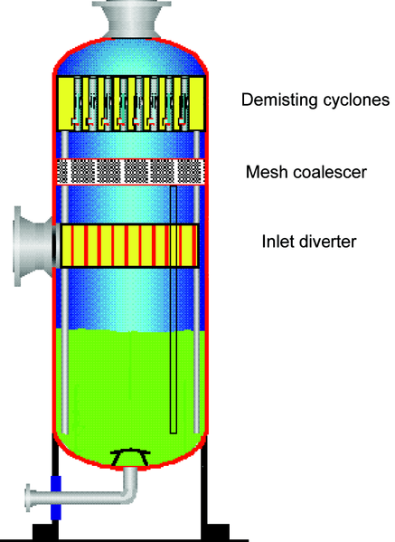
ig. 10a—Two-stage vertical scrubber with inlet diverter, mesh coalescer, and cyclone demisters (courtesy of CDS Separation Technologies Inc.).
---------
Single-stage cyclone scrubber
Fig. 10b is a single-stage cyclone scrubber for low liquid loading. The gas/liquid flows directly at the cyclones. This type of a scrubber is a compact unit with a three to five reduction in size and weight from a standard scrubber. Fig. 11 shows a schematic of a Gasunie cyclone separator. The separator is a stand-alone inlet cyclone in which the vessel shell itself is the outer wall of the cyclone. This separator is mainly used as a scrubber but can be applied for higher liquid loadings on the order of 10%v.
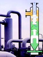
Fig. 11—Gasunie cyclonic scrubber (courtesy of CDS Separation Technologies Inc.).
----------
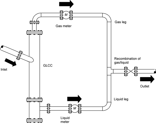
Fig. 10b—One-stage inline scrubber with demisting cyclones (courtesy of CDS Separation Technologies Inc.).
----------
Gas/liquid cylindrical cyclone
A gas/liquid cylindrical cyclone (GLCC) is a very simple and inexpensive centrifugal separation device. (See Fig. 12) Rough separation is achieved under low- g conditions, the swirl being generated by the sloped tangential inlet. The slope helps keep the level down during small slug occurrence. It is often used for bulk separation in conjunction with well testing as shown. The streams are temporarily separated, measured and analyzed, then recombined. With this arrangement, no level control is necessary because the levels are maintained by hydraulic balance.
ig. 12—GLCC separator (courtesy of Natco).
------------------
Multitube cyclone inline separator
A multitube cyclone inline separator, shown in Fig. 13, causes a wet gas flowstream to be divided between a number of cyclone tubes. As the gas stream enters a tube, it encounters a spin generator. The spin generator is a stationary device consisting of a hollow core and a radial arrangement of curved blades that divert the gas stream into a rotating flow pattern. In the tube downstream of the spin generator, liquid is separated from the gas by being slung out against the tube wall by centrifugal force. Near the end of each tube, the liquid film encounters a peripheral gap in the tube wall. This gap allows the liquid to be pulled out of the tube into the annular space around the tubes, where it falls to the bottom and is discharged under level control. The demisted gas stream continues through the tube, then recombines with that of the other tubes.
§ Fig. 13—Approximate shell length for vertical vessels (courtesy of CDS Separation Technologies Inc.).
References
Use this section for citation of items referenced in the text to show your sources. [The sources should be available to the reader, i.e., not an internal company document.]

