


Performance impediments
Foaming
When pressure is reduced on certain types of crude oil, tiny bubbles of gas are encased in a thin film of oil when the gas comes out of solution. This may result in foam, or froth, being dispersed in the oil and creates what is known as “foaming” oil. In other types of crude oil, the viscosity and surface tension of the oil may mechanically lock gas in the oil and can cause an effect similar to foam. Oil foam is not stable or long-lasting unless a foaming agent is present in the oil.
Whether crude oil is foamy is not well known. The presence of a surface active agent and process conditions play a part. The literature indicates organic acids as being a foaming agent. High-gravity oils and condensates typically do not result in foaming situations, as described by Callaghan et al.[1]
Foaming greatly reduces the capacity of oil/gas separators because a much longer retention time is required to adequately separate a given quantity of foaming crude oil. Foaming crude oil cannot be measured accurately with positive-displacement meters or with conventional volumetric metering vessels. These problems, combined with the potential loss of oil/gas because of improper separation, emphasize the need for special equipment and procedures in handling foaming crude oil.
The main factors that assist in “breaking” foaming oil are:
- Settling
- Agitation (baffling)
- Heat
- Chemicals
- Centrifugal force
These factors or methods of “reducing” or “breaking” foaming oil are also used to remove entrained gas from oil. Many different designs of separators for handling foaming crude oil have evolved. They are available from various manufacturers—some as standard foam handling units and some designed especially for a specific application.
Silicone- and fluorosilicone-based chemical defoamers are typically used in conjunction with cyclonic inlets to break foam. The chemical defoamer concentration is generally in the range of 5 to 10 ppm, but for many GOM crudes, 50 to 100 ppm is common.
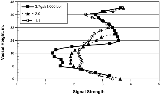
Fig. 4 is a gamma ray scan of a 48-in.-diameter horizontal gas separator showing the problems resulting from foam. The horizontal axis is signal strength, and the vertical axis is height within the separator. High signal strength indicates less mass or more gas. Less signal strength indicates more mass or liquid. As the chemical rate is decreased, the interface between gas/liquid becomes less defined. The bottom of the vessel becomes gassy (more signal), while the upper portion becomes foamy (less signal). Liquid carryover occurs as the foam is swept through the demister. Gas carry-under occurs as the bubbles cannot be separated.
Performance impediments
Fig. 5 shows a horizontal separator used to process foamy crudes. The fluids flow through inlet cyclones, where the centrifugal action helps break the large bubbles. A perforated plate downstream of the inlet cyclones aids in promoting uniform flow as well as demisting and defoaming. Demisting cyclones in the gas outlet remove large amounts of the liquid that results from a foamy oil layer. The foamy oil pad results from the small bubbles that cannot be removed in the inlet cyclones.
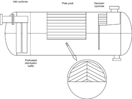
In between the perforated plate and the demister, high-surface internals such as plate or matrix packs are sometimes installed to break the large bubbles. As previously discussed, the theory behind the high-surface internals is that the bubbles will stretch and break as they are dragged along the surfaces. However, if most of the gas flows through the top portion of the pack, the foamy layer will not be sufficiently sheared, and the bubbles will meander through to the other end.
Paraffin
Paraffin deposition in oil/gas separators reduces their efficiency and may render them inoperable by partially filling the vessel and/or blocking the mist extractor and fluid passages. Paraffin can be effectively removed from separators by use of steam or solvents. However, the best solution is to prevent initial deposition in the vessel by heat or chemical treatment of the fluid upstream of the separator. Another deterrent, successful in most instances, involves the coating of all internal surfaces of the separator with a plastic for which paraffin has little or no affinity. The weight of the paraffin causes it to slough off of the coated surface before it builds up to a harmful thickness.
In general, paraffinic oils are not a problem when the operating temperature is above the cloud point (temperature at which paraffin crystals begin to form). The problems arise, however, during a shutdown, when the oil has a chance to cool. paraffin comes out of solution and plates surfaces. When production is restored, the incoming fluid may not be able to flow to the plated areas to dissolve the paraffin. In addition, temperatures higher than the cloud point are required to dissolve the paraffin.
Solids and salt
If sand and other solids are continuously produced in appreciable quantities with well fluids, they should be removed before the fluids enter the pipelines. Salt may be removed by mixing water with the oil, and after the salt is dissolved, the water can be separated from the oil and drained from the system.
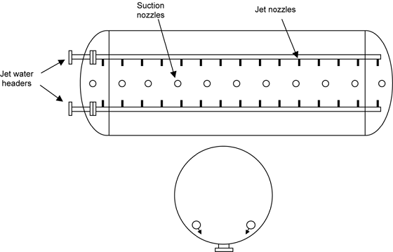
Vertical vessels are well suited for solids removal because of the small collection area. The vessel bottom can also be cone-shaped, with water jets to assist in the solids removal. In horizontal vessels, sand jets and suction nozzles are placed along the bottom of the vessel, typically every 5 to 8 ft. Inverted troughs may be placed on top of the suction nozzles as well to keep the nozzles from plugging. A sand-jet system is shown in Fig. 6. This type of system is sometimes difficult to use while the vessel is in operation because of the effect of the jetting and suction on separation and level control. For vessels that must be designed to enable sand jetting while in service, see the discussion
Corrosion
Produced well fluids can be very corrosive and cause early failure of equipment. The two most corrosive elements are hydrogen sulfide and carbon dioxide. These two gases may be present in the well fluids in quantities from a trace up to 40 to 50% of the gas by volume. A discussion of corrosion in pressure vessels is included in the page of water trea ting.
Sloshing
Because of the action of waves or ocean current on a floating structure, liquid contents in an oil/gas separator would be excited, which results in internal fluid sloshing motions. It is particularly a problem in long horizontal separators. Sloshing degrades the separation efficiency through additional mixing, resulting in liquid carry-over in the gas line, gas carry-under in the liquid line, and loss of level control. In three-phase separators, oil/water and gas/liquid separation efficiency is degraded. It is therefore necessary to design internal baffle systems to limit sloshing. Emphasis is generally placed on internals for wave dampening in gas-capped separators because of the larger fluid motions.
The liquid level changes from end to end must be considered in the design of the inlet and outlet devices. Too low a liquid level can result in gas blow-by of inlet cyclones, whereas too high a liquid level can cause siphoning of liquid through the mist extractor.
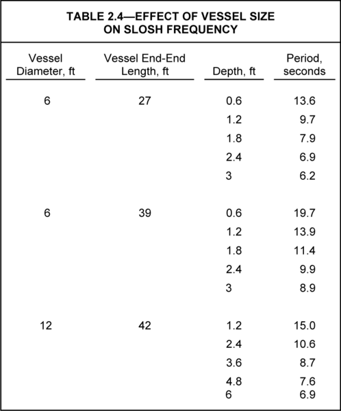
Table 3 gives some estimates of the natural period of the liquid for vessels undergoing lengthwise motions (sway). The periods are in the order of 10s, which is similar to the period found for floating platforms such as tension leg platforms (TLP) and floating production, storage and offloading (FPSO) vessels under a 10-year storm condition.
The alignment of the separators with the structure motion should be considered when designing the layout. For example, on TLP, the vessels are recommended to be aligned with their long dimension, perpendicular to the TLP prevailing motion. On ships, the magnitude and period of the pitch and roll should be considered when aligning the vessels. Normally, it is recommended to align the separators with their long dimension along the length of the ship.
The available literature, as described by Roberts et al., highlights two main features of wave-damping internals:
- Elimination of the gas/liquid interface
- Shifting of the natural sloshing frequency of the separator away from the platform frequency
On some ships, fuel tanks fill with sea water, as the fuel is spent, to prevent problems associated with sloshing.
Shifting the natural frequency is usually accomplished by segmenting the vessel with transverse baffles. The baffles are perforated, can be placed throughout the liquid phase, or can be placed in the region of the oil/water interface. However the following are major concerns:
- Vessel access
- Solids collection
- Mixing are major concerns
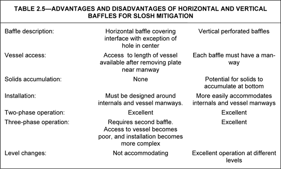
Horizontal perimeter baffles can be used, but they have disadvantages as well. Other baffle shapes include angled wings along the length of the vessel to mitigate waves because of roll as well as vertical perforated baffles down the length of the vessel. Table 4highlights the differences between horizontal and vertical baffles.
Level controls
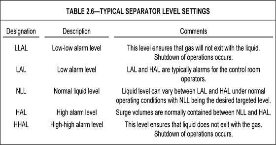
Stable control of the oil/water and gas/oil interfaces is important for good separation. The typical two-phase separator level settings are shown in Table 5. For three-phase operation, level settings are placed on both the oil/water interface and oil/gas interface levels
Typically, the spacing between the different levels is at least 4 to 6 in. or a minimum of 10 to 20 seconds of retention time. The location of the lowest levels must also consider sand/solids settling. These levels are typically 6 to 12 in. from the vessel bottom. Minimum water/oil pad thicknesses are approximately 12 in. Note that these minimum settings may dominate the vessel sizing as opposed to the specified retention times.
In a two- or three-phase horizontal separator with very little liquid/water, a boot or “double-barrel” separator configuration is used. All the interface controls are then located within the boot or lower barrel. Examples of these types of separators can be seen at Separa tor types.
To coerce the liquid to exit through the tube-wall gap, a slipstream of gas is also withdrawn. The slipstream is induced to exit through the gap by maintaining a lower pressure in the outer annular space than that which is inside the tubes. This is done by constructing ducts between the annular space and the hollow core pieces of all the spin generators. The tails of these hollow cores are, in turn, open to the low pressure of the newly generated gas vortices. A gas slipstream of about 5% is recycled out of the tubes to pull liquid out, then back to the spin generator and out its tail end, where it joins the main gas stream.
http://www.joboilfield.com/

