Cochran boiler
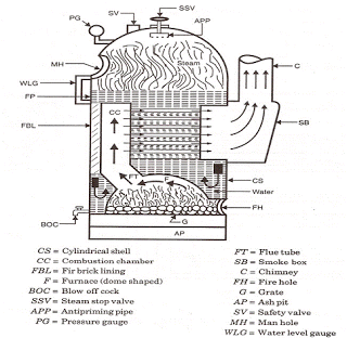
It is a multi-tubular vertical fire tube boiler having a number of horizontal fire tubes. T is the modification of a simple vertical boiler where the heating surface has been increased by means of a number of fire tubes.
It consists of 
- Shell
- Crate
- Fire box
- Flue pipe
- Fire tubes
- Combustion chamber
- Chimney
- Man-hole
Shell
It is hemispherical on the top, where space is provided for steam.
Grate
It is placed at the bottom of the furnace where coal is burnt.
Fire box (furnace )
It is also dome-shaped like the shell so that the gases can be deflected back till they are passed out through the flue pipe to the combustion chamber.
Flue pipe:
It is a short passage connecting the fire box with the combustion chamber.
Fire tubes:
A number of horizontal fire tubes are provided, thereby the heating surface is increased.
Combustion chamber:
It is lined with fire bricks on the side of the shell to prevent overheating of the boiler. Hot gases enter the fire tubes from the flue pipe through the combustion chamber.
Chimney:
It is provided for the exit of the flue gases to the atmosphere from the smoke box.
Manhole:
It is provided for inspection and repair of the interior of the boiler shell.
Normal size of a Cochran boiler:
Shell diameter – 2.75 meters:
Height of the shell – 6 meters.
Working of the Cochran boiler:
Coal is fed into the grate through the fire hole and burnt. Ash formed during burning is collected in the ashpit provided just below the grate and then it is removed manually.
The host gases from the grate pass through the flue pipe to the combustion chamber. The hot gases from the combustion chamber flow through the horizontal fire tubes and transfer the heat to the water by convection.
The flue gases coming out of fire tubes pass through the smoke box and are exhausted to the atmosphere through the chimney.
Smoke box is provided with a door for cleaning the fire tubes and smoke box.
The following mountings are fitted to the boiler:
Pressure gauge: this indicates the pressure of the steam inside the boiler.
Water gauge: this indicates the water level in the boiler. The water level in the boiler should not fall below a particular level, otherwise the boiler will be over heated and the tubes may burn out.
Safety valve: the function of the safety valve is to prevent an increase of steam pressure in the boiler above its normal working pressure.
Steam stop valve: it regulates the flow of steam supply to requirements.
Blow-off cock: it is located at the bottom of the boiler. When the blow-off cock is opened during the running of the boiler, the high pressure steam pushes (drains) out the impurities like mud, sand, etc., in the water collected at the bottom.
Fusible plug: it protects the fire tubes from burning when the water level in the boiler falls abnormally low.
Salient features of Cochran boiler:
- The dome shape of the furnace causes the hot gases to deflect back and pass through the flue. The un-burnt fuel if any will also be deflected back.
- Spherical shape of the top of the shell and the fire box gives higher area by volume ratio.
- It occupies comparatively less floor area and is very compact.
- It is well suited for small capacity requirements.
---------

La Mont Boiler Working and Construction
A forced circulation boiler was first introduced by La-Mont in the year 1925 which is used in Europe and America. This is a modern high pressure boiler (water tube type steam boilers) working on forced circulation system.
Working principle of La Mont Boiler
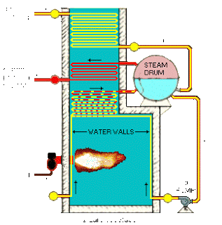
The image shows the flow circuit of La Mont Boiler.
I will explain working of each and every part in La Mont boiler one by one.
Steam separator drum
The la Mont boiler consists of a steam separator drum which is placed wholly outside the boiler setting . The drum receives a mixture of steam and water from the evaporator tubes and feed water from the economizer. The steam is separated from water in the drum.
Circulating pump
The water from the drum is then drawn to the circulating (centrifugal) pump through the down-comer. The pump circulates water (“forced circulation”) equal to 8 to 10 times the weight of steam evaporated. This prevents the tubes from being overheated.
Distributing header
The circulating pump delivers the feed water to the distributing header with orifices at a pressure above the drum pressure.
Evaporator
The header distributes water through orifices into the evaporator tubes acting in parallel. Orifice in the header controls the flow of water to the evaporator tubes. Here part of the water is evaporated and a mixture of steam and water from these tubes enters the drum.
Convection superheater
The steam produced in the boiler is nearly saturated. This steam as such should not be used in the steam turbine. The presence of moisture in it will cause corrosion of turbine blades, etc. to raise the temperature of steam and thereby to increase the turbine efficiency, superheater is used.
The principle of convection superheater is similar to steam generating tubes of the boiler. The hot flue gases at high temperature sweep over convection superheated tubes and raise the temperature of steam. Convection superheater thus receives heat from the flue gases flowing from the combustion chamber, entirely by convective heat transfer. Such a superheater may be more conveniently located since it is not necessary for it to “see” the furnace.
Saturated steam from the top of the drum enters the convection superheater placed in the path of the flue gases and is superheated.
Steam outlet
Superheated steam from the superheater passes out to the steam turbine through the steam outlet.
Economizer
The quantity of superheated steam thus delivered to turbine is continuously made up in the form of feed water. Feed water supplied by the feed pump is heated in the economizer on its way to the steam separator drum.
The economizer is a device used to preheat the feed water using the hot gases leaving the boiler. Before the gases are let off to the atmosphere, they are made to flow in a definite passage in the economizer so that some of the heat in the hot gases, which otherwise gets wasted, can be used to preheat the feed water. The preheated water requires only a small amount of heat to be supplied in the boiler, resulting in some saving of the fuel burnt. This results in an increase in the boiler efficiency.
Air preheater
Since the heat of the exit gases cannot be fully extracted through the economizer, the air preheater is employed to recover some of the heat escaping in these gases. These exit gases preheat the air from the blower in the air preheater. The preheated air is supplied to the furnace for combustion.
Capacity
The capacity of la-mont boiler is about 50 Tonnes/hr of superheated steam at a pressure of 170 kgf/sq.cm. and at a temperature of 500’C


